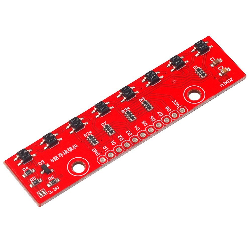
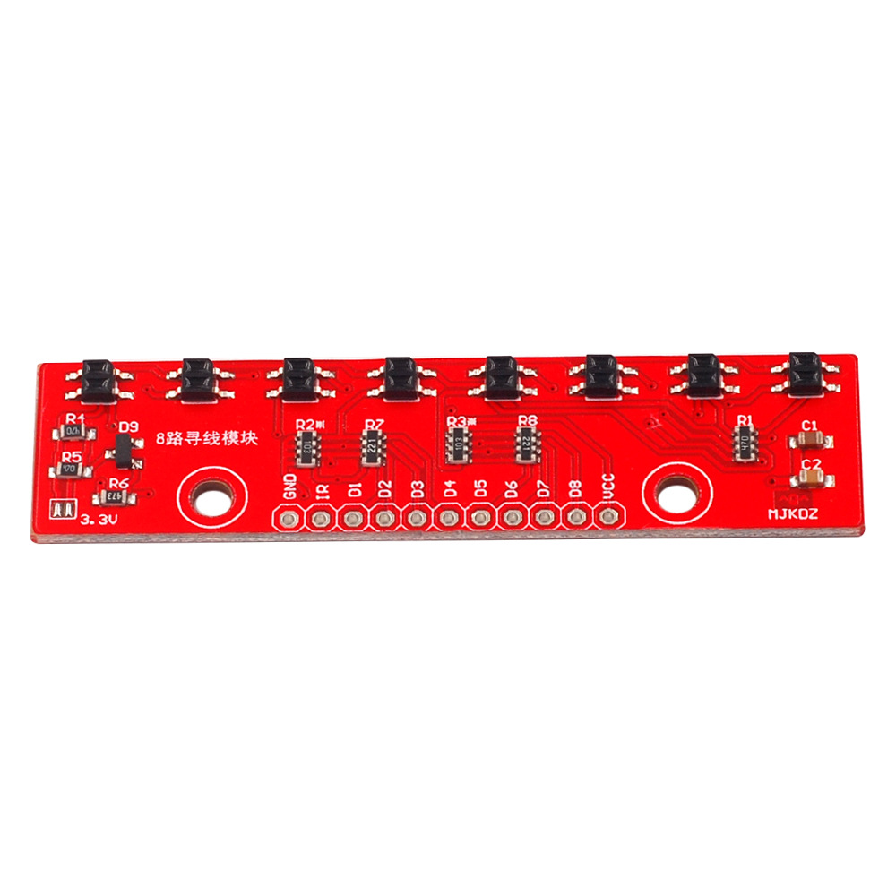
Cảm biến dò line 8 kênh QTR-8A là một module cảm biến sử dụng để phát hiện và theo dõi đường kẻ, thường được dùng trong các ứng dụng robot tự hành hoặc các hệ thống tự động hóa. Cảm biến này được trang bị 8 kênh quang để theo dõi chính xác vị trí của đường kẻ trên bề mặt, cho phép robot hoặc thiết bị xác định hướng di chuyển dựa trên độ phản xạ ánh sáng.
Thông số kỹ thuật Cảm biến dò line 8 kênh QTR-8A:
Đặc điểm nổi bật:
Ứng dụng:
Code tham khảo
#include <QTRSensors.h>
QTRSensors qtr;
const uint8_t SensorCount = 6;
uint16_t sensorValues[SensorCount];void setup()
{
// configure the sensors
qtr.setTypeAnalog();
qtr.setSensorPins((const uint8_t[]){A0, A1, A2, A3, A4, A5}, SensorCount);
qtr.setEmitterPin(2);delay(500);
pinMode(LED_BUILTIN, OUTPUT);
digitalWrite(LED_BUILTIN, HIGH); // turn on Arduino's LED to indicate we are in calibration mode// analogRead() takes about 0.1 ms on an AVR.
// 0.1 ms per sensor * 4 samples per sensor read (default) * 6 sensors
// * 10 reads per calibrate() call = ~24 ms per calibrate() call.
// Call calibrate() 400 times to make calibration take about 10 seconds.
for (uint16_t i = 0; i < 400; i++)
{
qtr.calibrate();
}
digitalWrite(LED_BUILTIN, LOW); // turn off Arduino's LED to indicate we are through with calibration// print the calibration minimum values measured when emitters were on
Serial.begin(9600);
for (uint8_t i = 0; i < SensorCount; i++)
{
Serial.print(qtr.calibrationOn.minimum[i]);
Serial.print(' ');
}
Serial.println();// print the calibration maximum values measured when emitters were on
for (uint8_t i = 0; i < SensorCount; i++)
{
Serial.print(qtr.calibrationOn.maximum[i]);
Serial.print(' ');
}
Serial.println();
Serial.println();
delay(1000);
}void loop()
{
// read calibrated sensor values and obtain a measure of the line position
// from 0 to 5000 (for a white line, use readLineWhite() instead)
uint16_t position = qtr.readLineBlack(sensorValues);// print the sensor values as numbers from 0 to 1000, where 0 means maximum
// reflectance and 1000 means minimum reflectance, followed by the line
// position
for (uint8_t i = 0; i < SensorCount; i++)
{
Serial.print(sensorValues[i]);
Serial.print('\t');
}
Serial.println(position);delay(250);
}
1. BẢO HÀNH
Bảo hành sản phẩm là: khắc phục những lỗi hỏng hóc, sự cố kỹ thuật xảy ra do lỗi của nhà sản xuất.
1.1. Quy định về bảo hành
– Sản phẩm được bảo hành miễn phí nếu sản phẩm đó còn thời hạn bảo hành được tính kể từ ngày giao hàng, sản phẩm được bảo hành trong thời hạn bảo hành ghi trên Sổ bảo hành, Tem bảo hành và theo quy định của từng hãng sản xuất liên quan đến tất cả các sự cố về mặt kỹ thuật.
– Có Phiếu bảo hành và Tem bảo hành của công ty hoặc nhà phân phối, hãng trên sản phẩm. Trường hợp sản phẩm không có số serial ghi trên Phiếu bảo hành thì phải có Tem bảo hành của CÔNG TY DOLA (kể cả Tem bảo hành gốc).
1.2. Những trường hợp không được bảo hành
– Sản phẩm đã hết thời hạn bảo hành hoặc mất Phiếu bảo hành.
– Số mã vạch, số serial trên sản phẩm không xác định được hoặc sai so với Phiếu bảo hành.
– Tự ý tháo dỡ, sửa chữa bởi các cá nhân hoặc kỹ thuật viên không phải là nhân viên CÔNG TY DOLA
– Sản phẩm bị cháy nổ hay hỏng hóc do tác động cơ học, biến dạng, rơi, vỡ, va đập, bị xước, bị hỏng do ẩm ướt, hoen rỉ, chảy nước, động vật xâm nhập vào, thiên tai, hỏa hoạn, sử dụng sai điện áp quy định.
– Phiếu bảo hành, Tem bảo hành bị rách, không còn Tem bảo hành, Tem bảo hành dán đè, hoặc Tem bảo hành bị sửa đổi (kể cả Tem bảo hành gốc).
– Trường hợp sản phẩm của Quý khách hàng dán Tem bảo hành của CÔNG TY DOLA hay nhầm lẫn thông tin trên Phiếu bảo hành, Phiếu mua hàng: Trong trường hợp này, bộ phận bảo hành sẽ đối chiếu với số phiếu xuất gốc lưu tại Công ty, hóa đơn, phần mềm của Công ty hay thông tin của nhà phân phối, hãng, các Quý khách hàng khác mua cùng sản phẩm cùng thời điểm, nếu có sự sai lệch thì sản phẩm của Quý khách không được bảo hành (có thể Tem bảo hành của Công ty bị thất thoát và bị lợi dụng dán lên thiết bị hay nhầm lẫn nhỏ khi nhập, in ra). Kính mong Quý khách hàng thông cảm!
– Bảo hành không bao gồm vận chuyển hàng và giao hàng.
2. BẢO TRÌ
Bảo trì, bảo dưỡng: bao gồm lau chùi sản phẩm, sửa chữa những hỏng hóc nhỏ có thể sửa được (không bao gồm thay thế thiết bị). Thời gian bảo trì, bảo dưỡng tùy thuộc vào sự thỏa thuận giữa DOLA và Quý khách hàng.